How To - Spokes

Measuring and Entering the Component Data
The following steps and measurements will give an exremely accurate spokelength. It is important to take all measurements with the utmost care. If the information inputted into the program is the result of perfect measurements, then perfect spoke lengths will be produced. All measurements must be taken in millimeters to .1 millimeter accuracy. If measurements differ between the left and right side of the same hub, as in a rear wheel, then separate calculations must be performed for each side. If you have never measured wheel components before, you may want to print these instructions out for easy reference.
Step 1. Choose the Wheel or Tire Size - This is an optional input which will calculate the Rim Correction Factor used in the Sutherland's Handbook for Bicycle Mechanics spoke calculation system. It uses the Effective Rim Diameter value to determine the Rim Correction Factor. This is useful for updating a Sutherland's Manual with information about a new rim that may have been introduced after the current manual was printed.
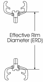 Step 2. Enter the Effective Rim Diameter (ERD) - Also called Rim Spoke End Diameter, this is the diameter from one spoke end to the opposite spoke end in a fully tensioned wheel. The measurement is actually from the base of the screw driver slot of one nipple to the same location on another nipple directly across the diameter of the rim. It can be measured by using a commercial product, such as the Wheelsmith Rim Rods, or by measuring using the steps below. Please note: This is a very important measurement and lack of accuracy will greatly affect the final spoke length! Measure carefully, double checking each step to insure accurate results.
- Carefully measure the outside diameter of the rim, from outside edge to outside edge, being careful to measure exactly in the center across the rim. To be sure the rim is round, measure in at least two locations 90 degrees apart. If the two measurements are different, measure in a third location and average the three measurements.
- Next, drop a spoke nipple into any hole in the rim. Using the depth gauge of the measuring caliper, measure from the top edge of the rim to the base of the screwdriver slot of the nipple. This represents where the end of the spoke should be when the wheel is fully tensioned.
- Using the measurement obtained in step 2, multiply the result by 2 and subtract that number from the measurement obtained in step 1 (the outside rim measurement). The result will be the Effective Rim Diameter (ERD).
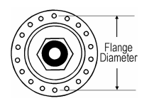
Step 3. Enter the Hub Flange Diameter - This is a measurement, in millimeters, between the center of one spoke hole to the center of another spoke hole on the opposite side of the same flange. Since it is difficult taking an accurate measurement from the center of a hole, it may be more accurate to measure from one edge of the hole to the same edge on the opposite hole. Use metric measuring calipers for the best results.
 Step 4. Enter the Hub Center To Flange Center Dimension - This dimension requires two measuring steps:
- First, measure the over-locknut dimension (O.L.D.) of the hub, from the outside face of the left locknut to the outside face of the right locknut in millimeters.
- Next, working with one side of the hub first, then the other, measure from the face of the locknut to the center of the flange on the same side of the hub, then subtract that number from half the over-locknut dimension using the following formula:
- Left Center to Flange Dimension O.L.D. / 2) - Left Locknut to Left Flange
- Right Center to Flange Dimension O.L.D. / 2) - Right Locknut to Right Flange
If using off-center spoke hole style rims you must also do the following:
- Perform the usual center to flange measurements on the hub.
- Then take a width measurement of the rim where the spoke holes are, from side wall to side wall across a hole.
- Divide the width measurement by 2 to get the location of the centerline of the rim.
- Then measure from the center of the rim to the centerline of the offset spoke holes (the imaginary line that runs between the offset holes in the rim). This value will be used in the last step.
- Finally, for the non-drive side, subtract the value derived from Step 4 from the non-drive side center-to-flange value, and conversely, add the value derived from step 4 to the drive side center-to-flange value. You then use those values as input for left and right center-to-flange in the spoke length calculator.
Step 5. Enter the Hub Spoke Hole Diameter - This is the diameter of the actual spoke holes in the flange. The default value of 2.5 mm works fine for most hubs. Hub spoke hole diameters range from 2.0 mm to 3.0 mm. Some higher quality hubs have smaller spoke holes so to achieve the ultimate in accuracy the default value can be changed.
Step 6. Choose the Number of Spokes - This is the total number of spokes in the wheel, even if you are calculating spoke lengths for only one side of the wheel.
Step 7. Choose the Number of Crosses - Choose the number of spoke crosses the wheel will have, i.e. 3 cross, 4 cross, etc. This is the number of times a spoke crosses another spoke during its travel from the hub to the rim. More crosses create a longer spoke, more tangent spoke, and more torsionally efficient wheel. Less crosses require a shorter spoke, but is less torsionally efficient. For this reason, most torsional wheels, like rear wheels and disk brake wheels, use 3 and 4 cross. Radial wheels (0 cross) should only be used in non-torsional applications, for example, non-disk brake front wheels.